Shenzhen Fanway Technology Co., Ltd.
PCB Assembly

PCB Assembly

Fanway specializes in delivering efficient and reliable end-to-end PCB assembly services, precisely tailored to your unique requirements to accelerate your product success.

Hybrid SMT THT Technology PCB Assembly Service
  • Hybrid SMT THT Technology PCB Assembly ServiceHybrid SMT THT Technology PCB Assembly Service

Hybrid SMT THT Technology PCB Assembly Service

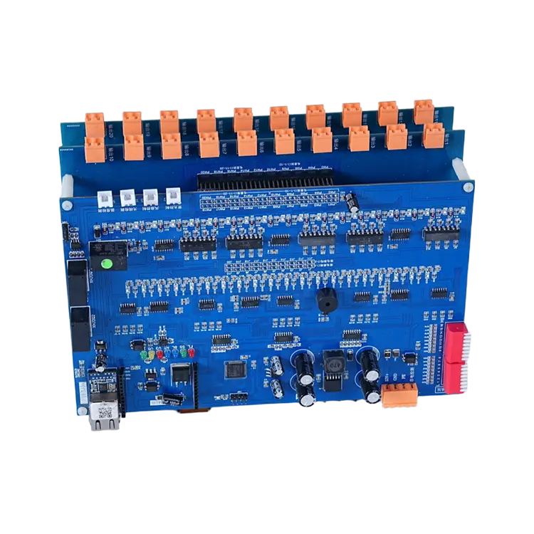
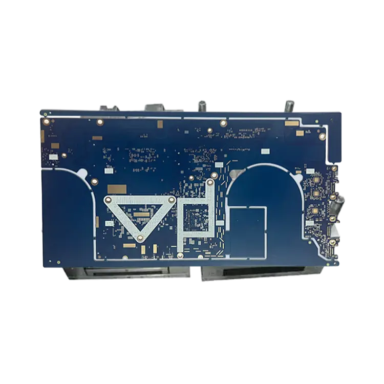
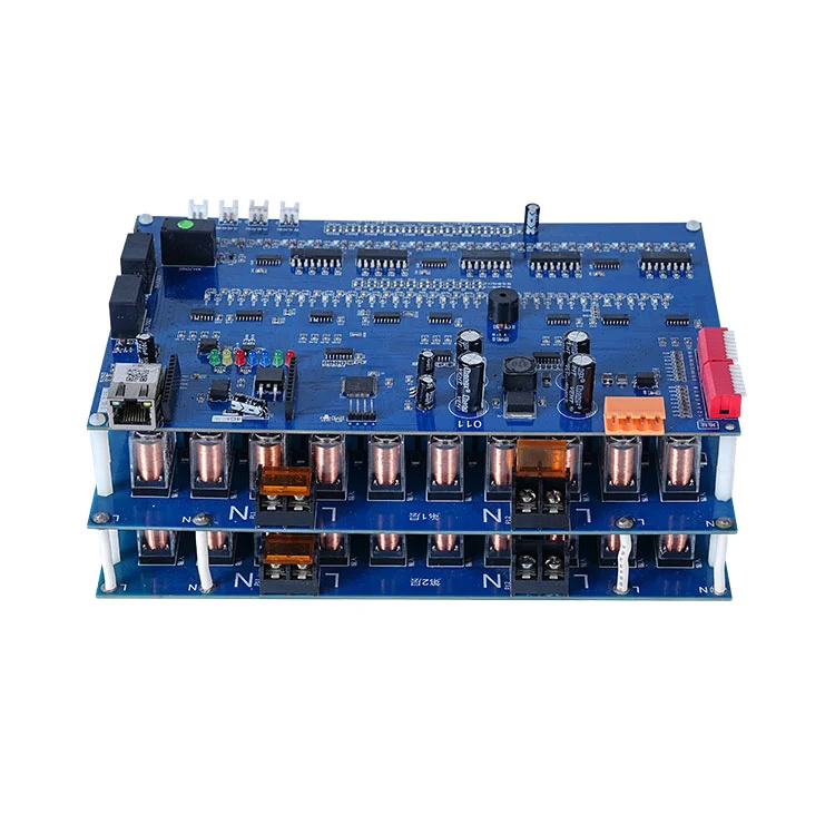
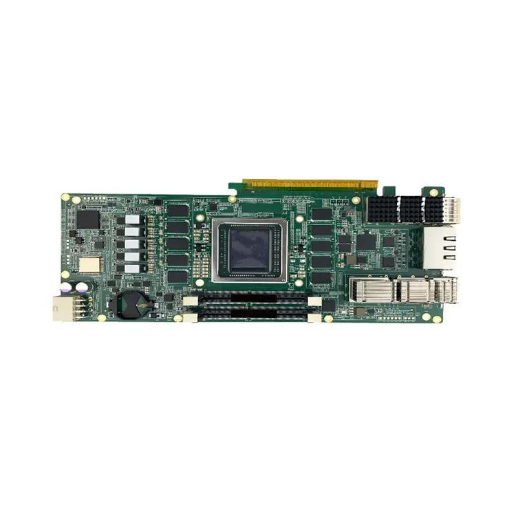
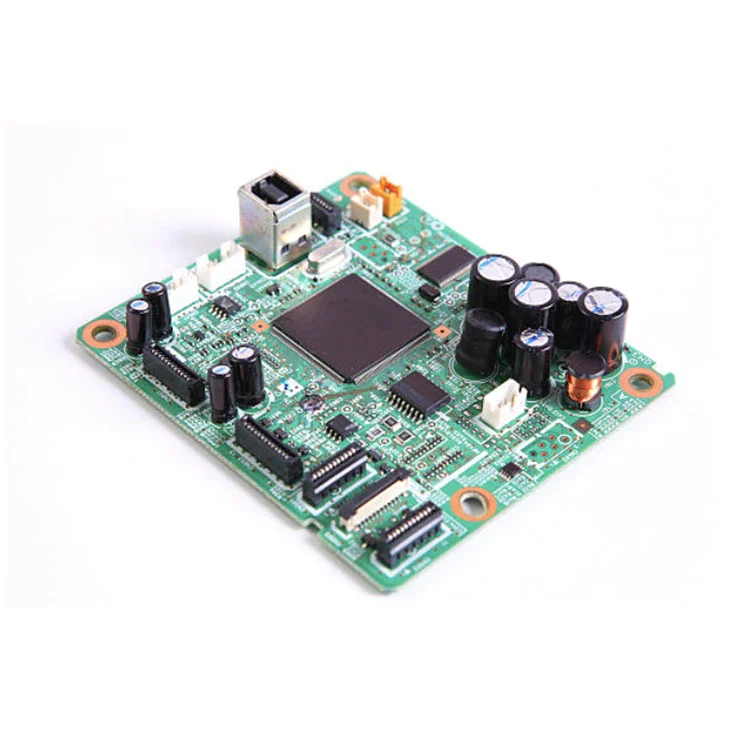
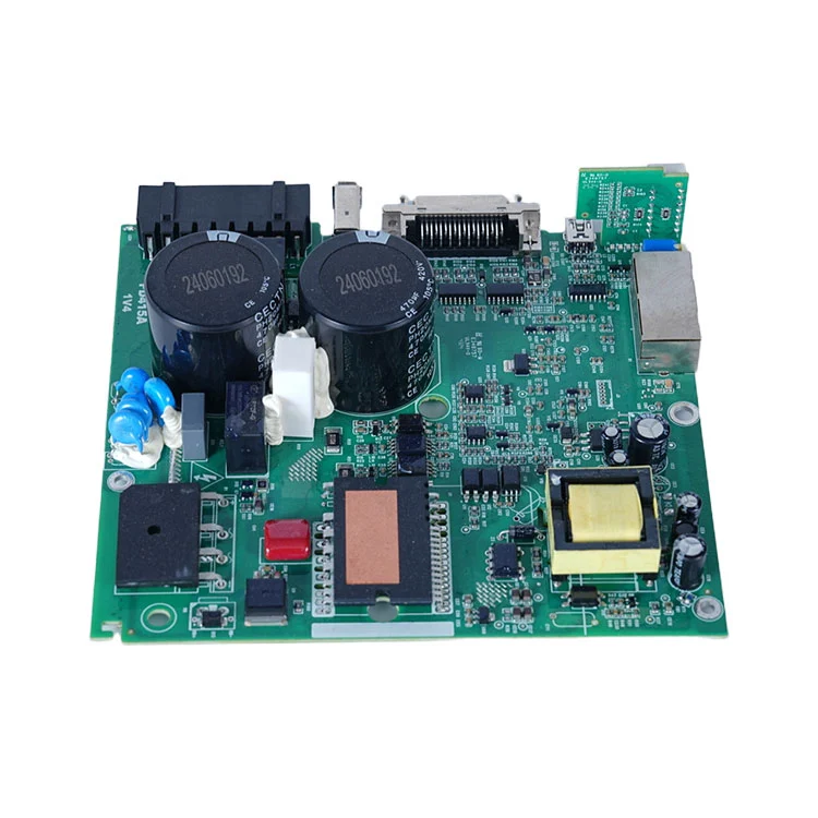
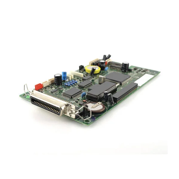
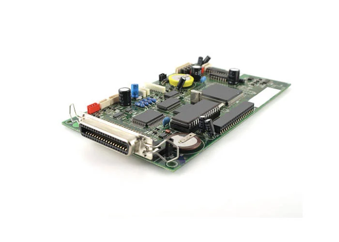
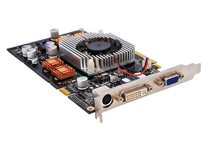
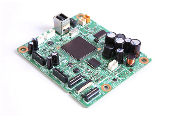
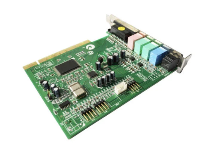
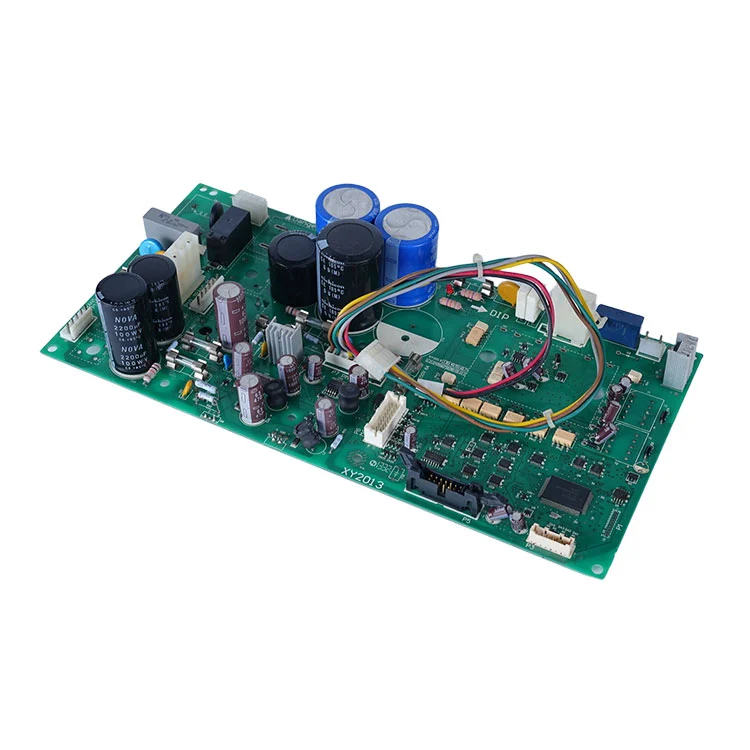
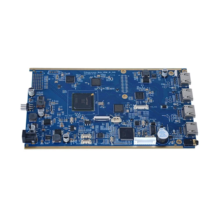
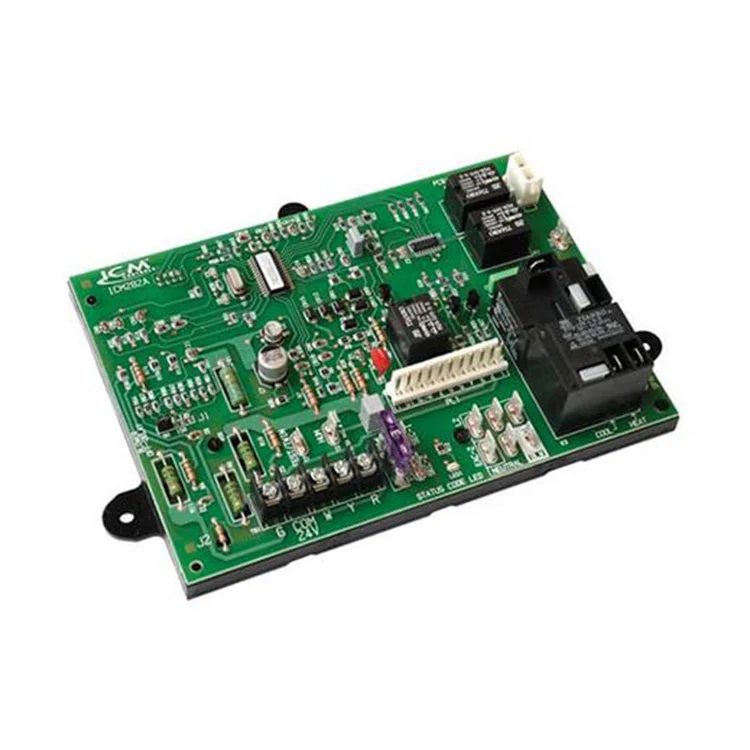
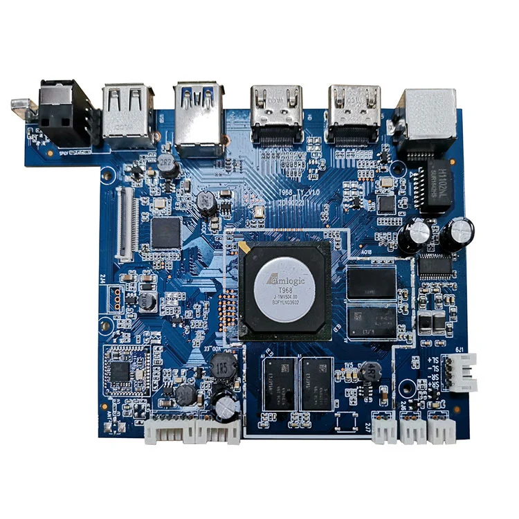
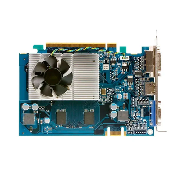
Fanway is a China mixed PCB assembly manufacturer, provides the Hybrid SMT THT Technology PCB Assembly Service that integrates surface-mount and through-hole processes on a single board. This approach is a practical response to boards that carry both fine-pitch ICs like BGAs, QFNs and large, mechanically demanding components including connectors, transformers, electrolytic capacitors.

Fanway's Hybrid SMT THT Technology PCB Assembly Service addresses a fundamental engineering challenge: boards that require both fine-pitch surface-mount devices for high-speed signal processing and through-hole components for power handling and mechanical durability. This service is not a simple combination of two separate processes; it is a carefully sequenced workflow that protects SMT joints during THT soldering, applies selective or wave soldering only after thermal protection, and delivers assemblies that meet IPC-A-610 Class 2 standards. With 12 years of mixed-technology experience, Fanway manages the critical interactions between SMT and THT zones, ensuring that dense chip placements coexist with large connectors and power devices without compromising yield or reliability.

When Mixed Assembly Needed?

Mixed assembly solves a fundamental design constraint: no single technology handles every component type optimally.

For signal integrity and density, SMT supports 01005 passives, 0.3mm-pitch BGAs, and high-speed interfaces. These components require precise solder paste printing and reflow profiles.

For power and mechanical resilience, THT handles connectors, relays, transformers, and large capacitors that must survive vibration, insertion cycles, and high currents. Through-hole joints provide pull strength exceeding 50N, something SMT cannot match.

When your PCB requires both categories, the Hybrid SMT THT Technology PCB Assembly Service becomes the only practical manufacturing route. Attempting to force all components into one technology either sacrifices reliability (using SMT for power devices) or wastes space (using THT for fine-pitch ICs).

How to Know If Your Project Needs Mixed Assembly?

Review your bill of materials. If it contains both of the following groups, mixed assembly is required.

SMT group: BGA, QFP, QFN, LGA, chip resistors/capacitors (0402, 0603), or any component with no leads passing through the board.

THT group: DIP ICs, pin headers, terminal blocks, large electrolytic capacitors, power MOSFETs with through-hole tabs, transformers, or any component requiring mechanical fixation through the board.

Boards with both groups cannot be efficiently assembled using SMT alone (THT components cannot be placed by pick-and-place) nor THT alone (fine-pitch SMT components cannot be wave-soldered without bridging). The Hybrid SMT THT Technology PCB Assembly Service is the designed solution for this exact scenario.

Our Mixed Assembly Work Flow

We follow a fixed sequence to protect SMT joints during THT soldering.

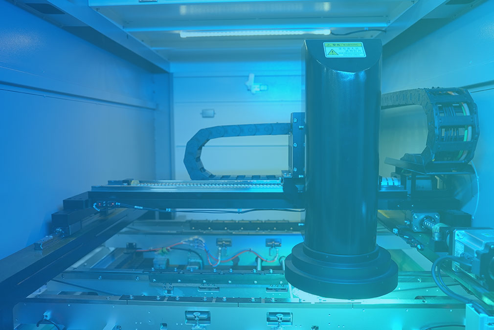
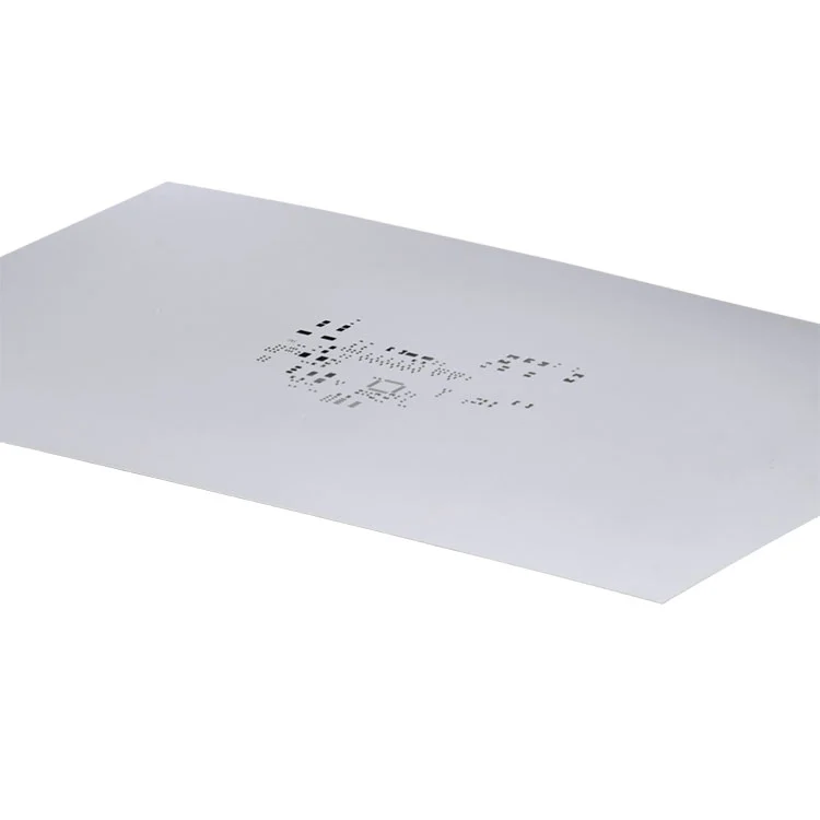
Step 1: Solder paste printing and SMT placement. Stencil printing applies paste only to SMT pads. For mixed boards, we use step stencils to adjust paste thickness across different zones. High-speed placement machines mount SMT components first.

Step 2: Reflow soldering. The board passes through a reflow oven to complete SMT joints. This step must occur before THT insertion, because reflow temperatures would damage most THT components (especially plastic-bodied connectors).

Step 3: THT insertion. Operators or automated insertion machines place THT leads through plated holes. Components are seated flush with the board; leads are kept straight. Insertion force is controlled to avoid cracking nearby SMT solder joints or warping the PCB.

Step 4: Wave or selective soldering. For boards with many THT components, wave soldering completes all joints in a single pass. For dense mixed layouts with SMT components close to THT pads, we apply selective soldering. Only the THT pads receive solder, with a smaller wave height (2-5mm vs. 8-12mm conventional) to minimise thermal impact on surrounding SMT joints.

Step 5: Trimming, cleaning and inspection. Excess leads are trimmed, flux residues cleaned, followed by AOI visual inspection, X-ray for hidden joints (BGAs, LGAs), and functional testing.

Design Rules That Determine Yield

Three DFM rules directly affect mixed assembly success.

Zone separation: keep at least 3mm clearance. Place THT components (connectors, large capacitors) near board edges or corners; place fine-pitch SMT devices (BGAs) away from the THT zone. A minimum 3mm gap prevents mechanical interference during insertion and solder splash during wave soldering.

Hole diameter: allow 0.1-0.2mm lead clearance. THT pad holes should be 0.1-0.2mm larger than the component lead diameter. Too tight and insertion becomes difficult or impossible; too loose and the component shifts, leading to poor solder fill or insufficient annular ring contact.

Thermal relief on large copper planes: THT pads connected to ground or power planes must use thermal relief spokes. Without them, the copper plane conducts heat away too quickly, causing cold solder joints. Additionally, SMT pads near wave-soldering zones should be covered with high-temperature tape to prevent solder bridging.

Applications 

Hybrid SMT THT Technology PCB Assembly Service is not a universal choice; it is mandatory in these sectors.

Automotive electronics: ECUs, BMS, ADAS modules combine high-density processors (SMT) with high-current connectors and relays (THT) that endure vibration and thermal cycling.

Industrial controls and power supplies: PLCs, servo drives, and industrial power modules use SMT for control logic and THT for power MOSFETs, transformers, and large capacitors that require effective heat sinking.

Medical devices: Patient monitors and diagnostic equipment rely on SMT for sensor front-ends and THT for power connectors and frequently-mated interfaces where mechanical durability is critical.

Aerospace and defense: High-reliability systems specify THT for all connections subject to shock and vibration, while SMT handles processing cores. Mixed assembly is the only way to meet both requirements on a single board.

Why Choose Fanway for Mixed Assembly?

1. 12 years of dedicated mixed-technology experience. We have specialised in SMT-THT mixed assembly since our founding. Our team understands exactly which layouts cause wave-soldering bridges, which insertion forces crack SMT joints, and which thermal profiles protect both technologies. This knowledge comes only from years of production data, not from textbooks.

2. IPC-A-610 Class 2 and ISO 9001:2015 certified. Every board goes through AOI, X-ray, and functional testing. For medical and automotive clients, we provide full traceability compliant with ISO 13485 and IATF 16949.

3. One-stop service from DFM to delivery. We review your Gerber and BOM, procure components, perform SMT and THT assembly, and conduct final testing. You receive a fully assembled, tested board, with no need to coordinate multiple vendors.

4. Flexible volumes from prototype to high-volume. No NRE for standard mixed assemblies. For complex boards, we provide engineering review and process optimisation before production starts.

FAQ

Q: What is the typical lead time for mixed assembly?
A: Prototypes take 5-7 working days. Small volumes (under 1000 pcs) take 7-10 days. Large volumes are evaluated case by case, typically 10-15 working days.

Q: When must selective soldering be used instead of wave soldering?
A: When fine-pitch SMT components (BGAs, QFNs) are within 5mm of THT pads, or when THT components are heat-sensitive (e.g., connectors with plastic housings). Selective soldering applies heat only to the THT joints, protecting nearby SMT devices.

Q: Does mixed assembly require special PCB material?
A: Standard FR-4 is sufficient for most cases. However, if the board carries high-power THT components (transformers, power MOSFETs), we recommend high-Tg material (Tg ≥ 150°C) to withstand wave-soldering thermal shock.

Q: Can SMT and THT components be placed on the same board side?
A: Yes. Placing both on the top side is common, leaving the bottom side clean for wave soldering. Maintain at least 2-3mm clearance between SMT pads and THT holes.

Q: Does Fanway support lead-free soldering?
A: Yes. Our reflow and wave soldering systems are fully compatible with SAC305 and other lead-free alloys, with temperature profiles set accordingly.

Need a mixed assembly assessment for your project? Send your Gerber files and BOM to our engineering team. We will provide a DFM report and quotation within 24 hours.

Hybrid SMT THT Technology PCB Assembly Service

Product Application Case

Nuomiglue Com

Aerospace & Defense

Nuomiglue Com

Automation Electronics

Nuomiglue Com

Medical Devices

Nuomiglue Com

Telecommunications


Hot Tags: Hybrid SMT THT Technology PCB Assembly Service
Send Inquiry
Contact Info
  • Address

    Building 3, The First Industrial Zone of Mingjinhai, Shiyan Street, Bao'an District, Shenzhen, Guangdong, China, Zip Code:518108

For inquiries about printed circuit board, electronics manufacturing, pcb assembly please leave your email to us and we will be in touch within 24 hours.
X
We use cookies to offer you a better browsing experience, analyze site traffic and personalize content. By using this site, you agree to our use of cookies.Privacy Policy
RejectAccept