Shenzhen Fanway Technology Co., Ltd.
News

News

Why Are Printed Circuit Boards the Backbone of Every Smart Device Today?

2025-10-16
  1. What is a Printed Circuit Board & Why It Matters

  2. How to Choose the Right PCB: FR4 vs. Rigid-Flex

  3. Deep Dive: FR4 PCB Parameters and Applications

  4. Deep Dive: Rigid Flex PCB Parameters and Applications

  5. Common Questions about Printed Circuit Board (PCB)

  6. Why Choose Us (Fanyway) & Contact Us

What is a Printed Circuit Board & Why It Matters

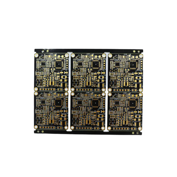
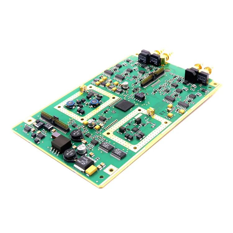
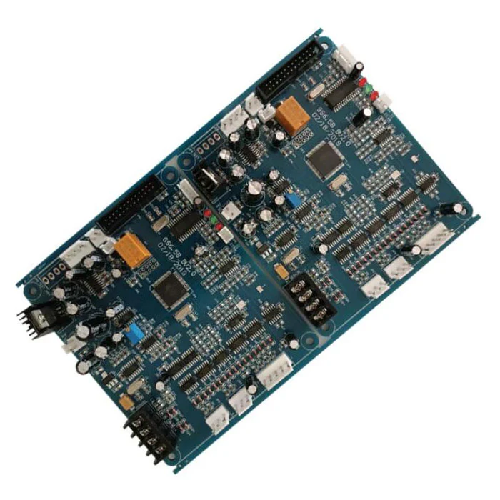
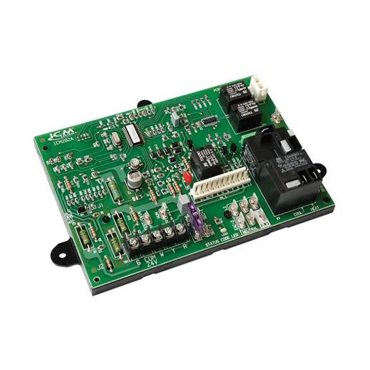
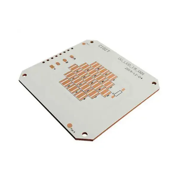
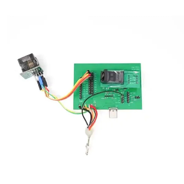
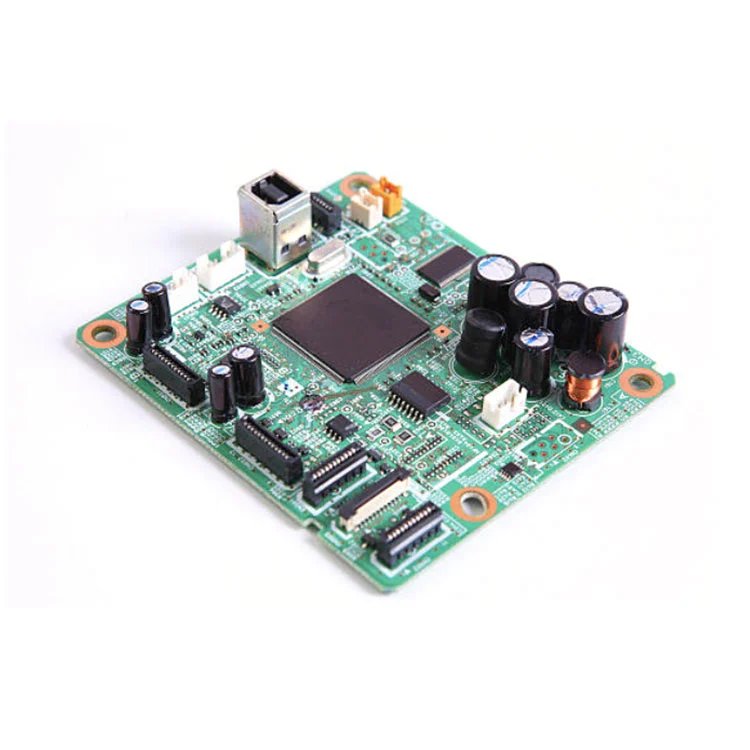
Printed Circuit Board (PCB) is the backbone of virtually all electronic devices—from consumer gadgets to industrial control systems. The board provides the mechanical support and electrical interconnection among electronic components. In today’s electronics-driven world, the design, material, and fabrication quality of a PCB are critical for performance, reliability, and cost.

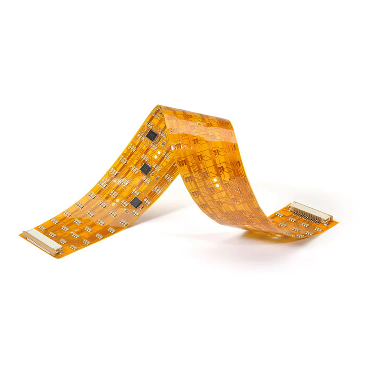
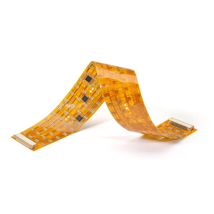
FPC PCB

Why Printed Circuit Boards Are Critical

  • They provide a compact, repeatable, reliable way to interconnect components.

  • They ensure signal integrity, power distribution, and thermal management.

  • With trends like miniaturization, 5G, AI, and IoT, advanced PCBs (e.g., HDI, rigid-flex) are becoming central to innovation.

  • The global PCB market is projected to reach USD ~117.53 billion by 2032, reflecting strong demand.

How to Choose the Right PCB: FR4 vs. Rigid-Flex

When selecting a PCB, you will commonly face a decision between FR4 (rigid) and Rigid-Flex (a hybrid of rigid + flexible). The choice depends on your product’s mechanical, electrical, and design constraints. Below are guiding “how / why / what” questions to help you decide:

Consideration Key Question Typical Guidance
Mechanical Stress & Bending How much flex or bending will the board experience in its lifecycle? Use Rigid-Flex if frequent bending or folding is needed; FR4 if board stays flat.
Space & Weight Constraints Why is weight or compactness critical? Rigid-Flex can reduce the need for connectors and inter-board wiring, saving space and weight.
Cost & Yield What is your budget and expected volume? FR4 is simpler and cost-effective at high volumes; Rigid-Flex has higher process complexity and cost.
Signal Integrity & Layer Count How many layers / how dense are your traces? Both can support high layer count, but rigid-flex may help with routing in constrained spaces.
Thermal, Vibration, Reliability Why prioritize durability and reliability? Rigid-Flex often performs better under shock and vibration, but must be designed carefully.

Let’s now examine in detail the two variants.

Deep Dive: FR4 PCB Parameters and Applications

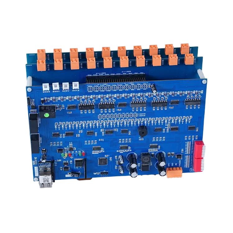
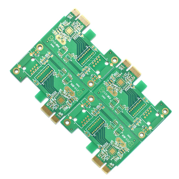
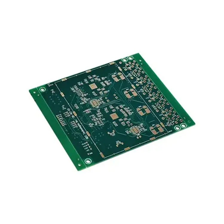
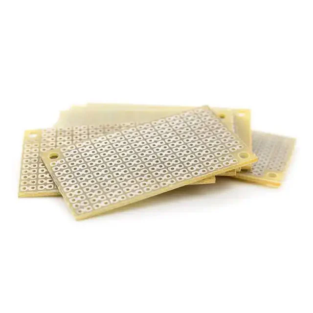
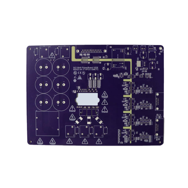
FR4 is the most commonly used substrate for rigid PCBs. “FR” stands for Flame Retardant, and “4” is a grade of material. It consists of woven fiberglass cloth with an epoxy resin binder.

FR4 PCB

Key Electrical & Physical Parameters

Below is a table of typical FR4 PCB parameters (these numbers may vary by supplier and Tg grade):

Parameter Typical Value / Range Notes / Importance
Dielectric constant (Dk) 3.8 – 4.8 (at 1 MHz) Affects impedance control and signal delay.
Dissipation factor (Df) ~0.009 (at 1 MHz) Loss tangent: signal loss in high frequency.
Electrical strength 800 – 1800 V/mil Dielectric breakdown strength.
Tg (Glass Transition Temp) 130 °C, 140 °C, 150 °C, 170 °C Higher Tg gives better thermal reliability.
Board thickness 0.4 mm – 3.2 mm (common) Depends on mechanical / fit constraints.
Copper thickness 1 oz (≈35 µm), 2 oz, 3 oz, 4 oz Heavier copper for higher current paths.
Min trace / spacing ~4 mil (0.1 mm) or better Dependent on manufacturing capability.
Surface finish ENIG, HASL, OSP, Immersion Ag, etc. Affects solderability, reliability.

Applications & Strengths of FR4 PCB

  • Consumer electronics (smartphones, wearables, appliances)

  • Industrial control boards, AD boards, power supplies

  • When the board remains flat, without required folding or flex

Limitations of FR4

  • Cannot bend or flex without risking crack or delamination (due to rigid glass+epoxy structure)

  • For compact, multi-segment electronics needing flexible interconnects, rigid-flex may be preferred

Deep Dive: Rigid-Flex PCB Parameters and Applications

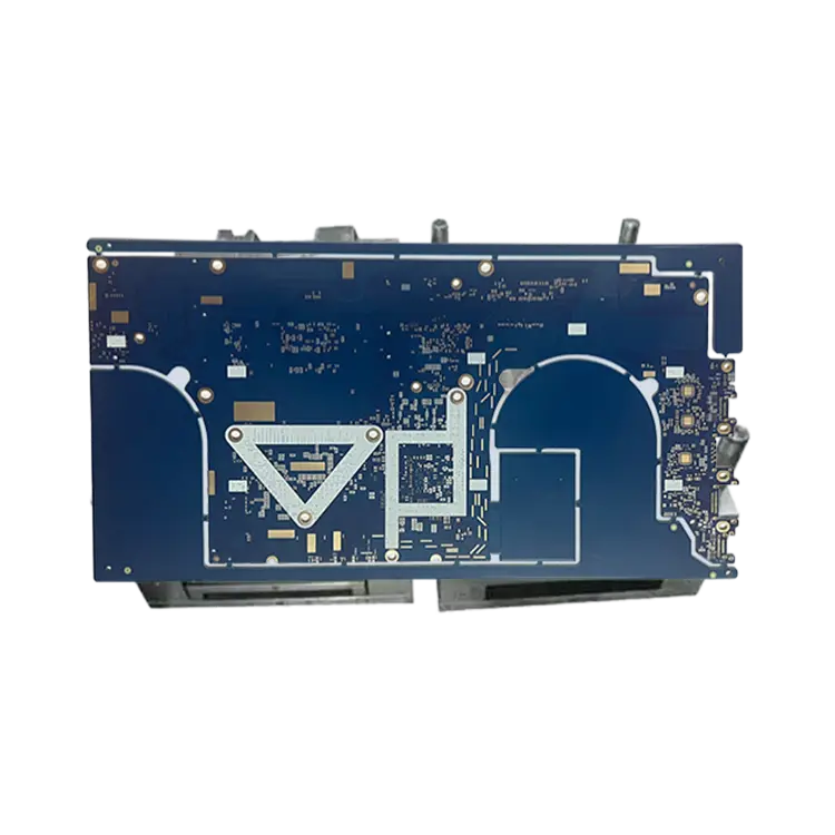
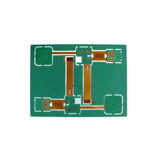
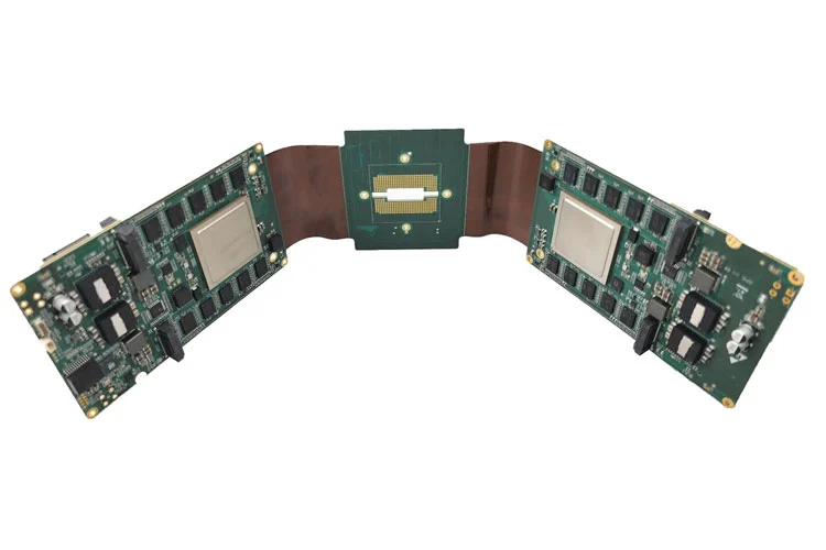
Rigid-Flex PCB combines rigid circuit sections (typically FR4) and flexible circuit sections (polyimide, polyester, etc.) in one integrated board. It enables flexing, folding, and a 3D structure while preserving rigid support for component mounting.

Rigid Flex PCB

Core Design & Process Notes

  • Design must carefully manage flex zones (bend radius, layer stacking, copper transitions)

  • The rigid and flex layers are laminated through controlled bonding and adhesion treatments.

  • Typical flex materials: polyimide films, coverlay films, adhesive layers

  • Fold angle per layer is limited (e.g., polyimide often ~0.5–2° per layer).

Typical Specifications & Capabilities

From industry references:

Item Parameter / Capability Notes
Rigid + Flex Board Thickness 0.25 mm up to 6.0 mm (combined) Depends on layer combinations and structure
Layers Up to 32 layers in some designs Multi-layer rigid + flex combining
Min trace / spacing 0.075 mm / 0.075 mm (≈ 3 mil) High-density flex region
Min hole size / pad size 0.10 mm / 0.35 mm For microvias, through-holes etc.
Max copper thickness 4 oz (rigid part) For rigid section heavy currents
Flex copper (flex part) 0.5 – 2 oz Lighter copper on flex area
Surface finish options ENIG, immersion Ag, OSP, HASL, etc. For both rigid and flex sections
Adhesion & lamination Special adhesion prep (plasma, brown oxide) To ensure flex-rigid bonding

Strengths & Applications of Rigid-Flex

  • Excellent in high vibration, shock, constrained spaces (e.g. aerospace, medical devices)

  • Reduces/eliminates connectors and inter-board wiring

  • Simplifies assembly by integrating rigid and flexible functions in one piece

  • Allows 3D circuit folding or multi-plane structure

Challenges & Costs

  • Higher manufacturing complexity, greater yield risk

  • Requires thoughtful design especially in flex zones (bend radius, stress relief)

  • Cost per board is higher, but system cost may reduce due to fewer connectors, cables, assembly steps

Common Questions About Printed Circuit Board (PCB)

Q1: How thick should a PCB be for my application?
A1: PCB thickness depends on mechanical, thermal and space constraints. Typical rigid FR4 boards range from 0.4 mm to 3.2 mm. In rigid-flex designs, combined thickness is often between 0.25 mm to 6.0 mm. The thinner the board, the more flexibility, but mechanical stability decreases.

Q2: Why choose rigid-flex over separate rigid and flex boards?
A2: Rigid-flex reduces connectors, wiring, and assembly steps; improves reliability under vibrations, and enables compact 3D folding. It integrates both rigid mounting zones and flexible sections in one board.

Q3: What electrical properties of FR4 most affect signal integrity?
A3: The dielectric constant (Dk) affects impedance and propagation velocity; the dissipation factor (Df) affects signal loss, especially at high frequency; copper thickness and trace geometry also play critical roles.

Why Choose Fanyway & Contact Us

At Fanyway, we specialize in designing and manufacturing high-performance Printed Circuit Board solutions tailored to rigorous applications. Whether you need standard FR4 rigid PCBs or complex Rigid-Flex boards, our engineering team applies decades of expertise to optimize layout, stack-up, material selection, and manufacturing strategy.

We adhere to strict quality and reliability standards, conforming to IPC guidelines, and support advanced processes like HDI, microvia, and controlled impedance. Our competitive edge lies in balancing cost, yield, and advanced capability for your product needs.

If you’re exploring whether to use FR4 or rigid-flex in your next design, or need to prototype or scale production, Fanyway is ready to help. Contact us today to discuss your project requirements and get a quote.

Related News
X
We use cookies to offer you a better browsing experience, analyze site traffic and personalize content. By using this site, you agree to our use of cookies. Privacy Policy
Reject Accept