Shenzhen Fanway Technology Co., Ltd.
News

News

How Do Printed Circuit Boards Power Modern Electronics?

2025-09-30

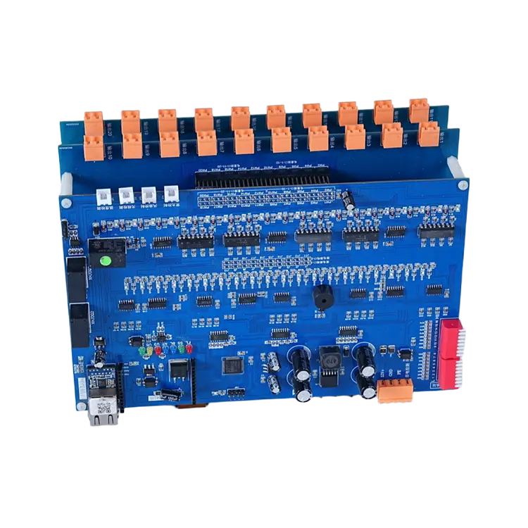
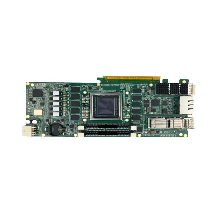
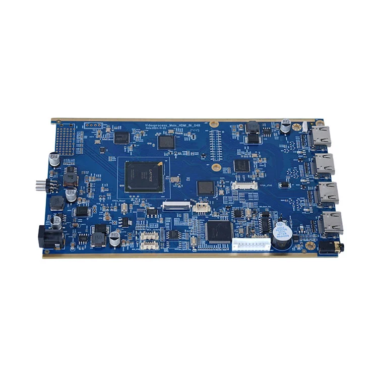
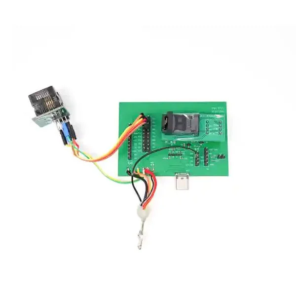
Printed Circuit Boards (PCBs) are the silent backbone of today’s electronics. Whether in a smartphone, automotive control system, medical scanner, or aerospace navigation module, PCBs provide the physical and electrical foundation that connects all components. Understanding how they work begins with recognizing the shift they brought to technology. Before PCBs, wiring was done manually with point-to-point connections. This method was not only prone to errors but also limited scalability. PCBs solved these issues by offering standardized and layered structures that ensure compact design, reliability, and mass production efficiency.

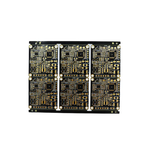
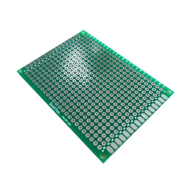
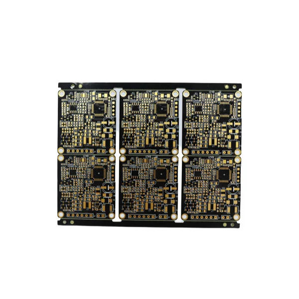
FR4 PCB

So, how exactly do they work? At their core, PCBs serve three primary purposes:

  1. Mechanical support – securing components in place.

  2. Electrical connections – providing conductive pathways for current flow.

  3. Signal integrity – ensuring that electronic signals travel with minimal loss or interference.

The construction involves substrates, typically FR4 fiberglass or other materials, that act as the insulating layer. On top of this, copper foils are laminated, etched into pathways, and plated with protective finishes. The end result is a meticulously designed board where resistors, capacitors, microchips, and connectors can be mounted.

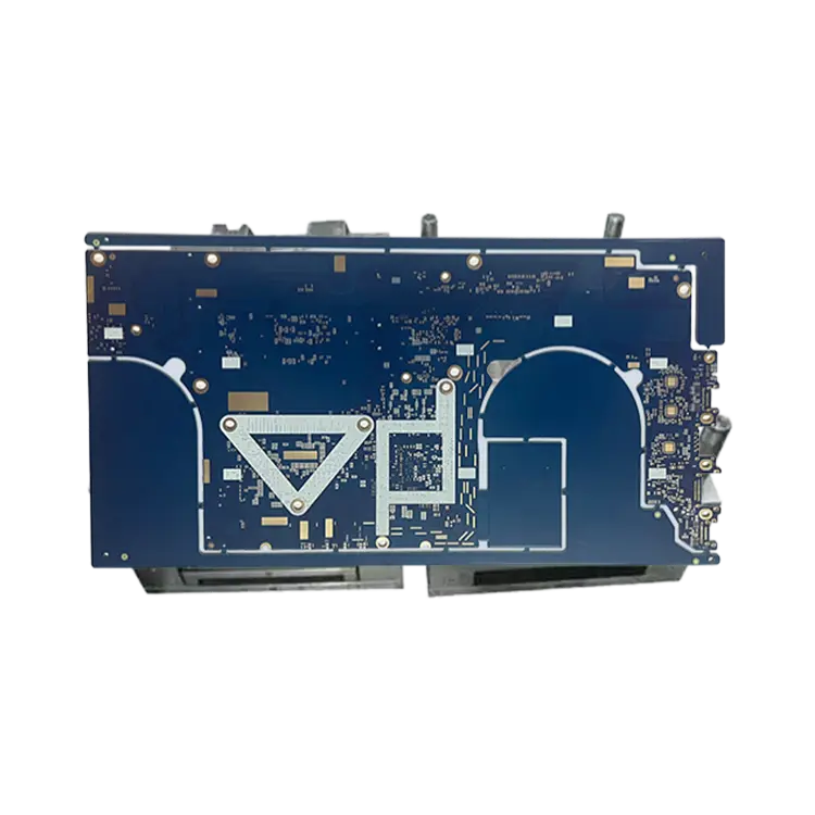
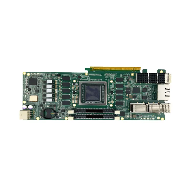
PCBs can be single-sided, double-sided, or multilayered depending on the complexity of the design. Multilayer PCBs—sometimes reaching more than 40 layers—are essential for advanced computing and telecommunications equipment, where signal routing density is critical. They incorporate vias (vertical interconnects) that allow signals to pass through different layers while maintaining performance integrity.

Heat management is another crucial role of PCBs. By designing thermal vias, heat sinks, or special copper pours, manufacturers ensure that sensitive components remain within safe operating temperatures. Without such design considerations, the risk of system failure increases significantly.

How Different PCB Types Meet Industry Demands

Industries rely on various types of PCBs tailored to specific applications. Understanding how these variations function provides insights into why PCBs remain indispensable in global electronics manufacturing.

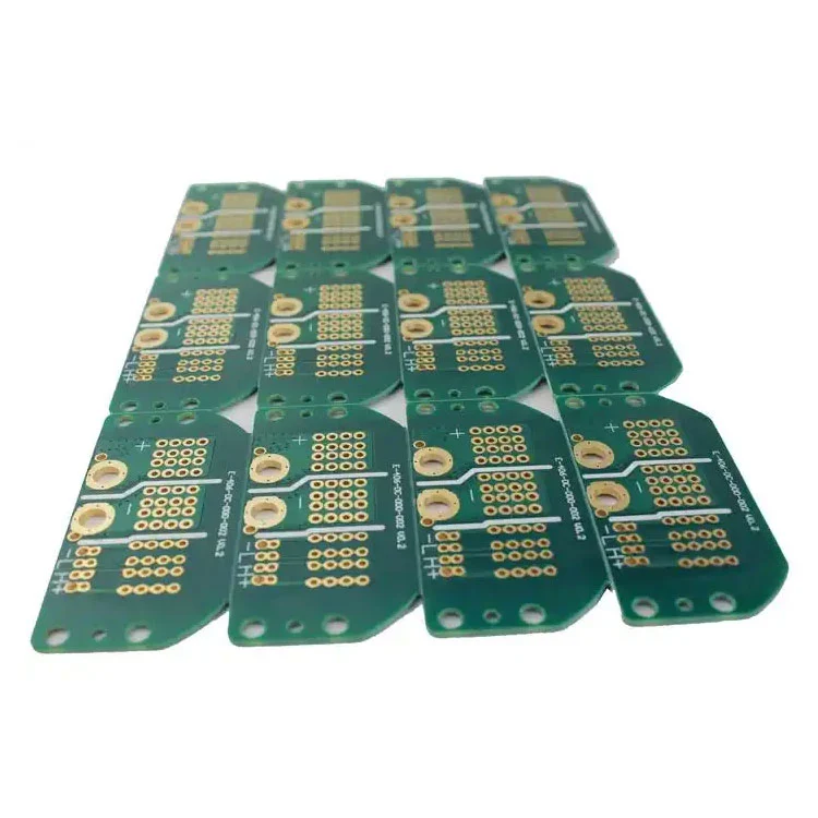
  • Single-Sided PCBs: These are the simplest type, with copper tracks on only one side of the board. They are cost-effective and widely used in calculators, radios, and simple consumer electronics.

  • Double-Sided PCBs: Featuring copper tracks on both sides, they allow more complex circuit designs. Components can be mounted on both sides, increasing density.

  • Multilayer PCBs: Comprising three or more layers of conductive copper, these boards handle highly complex applications. Smartphones, advanced medical devices, and aerospace electronics often rely on these.

  • Rigid PCBs: Built on solid substrates, they offer stability and durability, making them common in most electronic devices.

  • Flexible PCBs: Constructed using bendable materials like polyimide, they can twist and fold, ideal for wearables and compact electronics.

  • Rigid-Flex PCBs: A hybrid that combines rigid and flexible areas, offering structural stability and design flexibility simultaneously.

  • High-Frequency PCBs: Made with specialized materials, they ensure signal accuracy for applications like telecommunications and radar systems.

To highlight professional product parameters clearly, here is a summary table:

Parameter Typical Range/Specification Application Example
Base Material FR4, Polyimide, CEM-1, Rogers Consumer electronics, automotive, RF equipment
Copper Thickness 0.5 oz – 6 oz Power boards, industrial control
Layer Count 1 – 40+ From toys to supercomputers
Surface Finish HASL, ENIG, OSP, Immersion Silver, Immersion Tin Improves solderability, corrosion resistance
Minimum Trace Width/Spacing 2 – 4 mils (advanced designs below 2 mils possible) High-density interconnect (HDI) devices
Operating Temperature -55°C to +150°C (special designs up to 200°C+) Aerospace, military, industrial control
Dielectric Constant (Dk) 2.2 – 4.5 depending on material High-frequency signal transmission
Thermal Conductivity 0.25 – 2.0 W/mK (depending on substrate) Heat-sensitive circuits

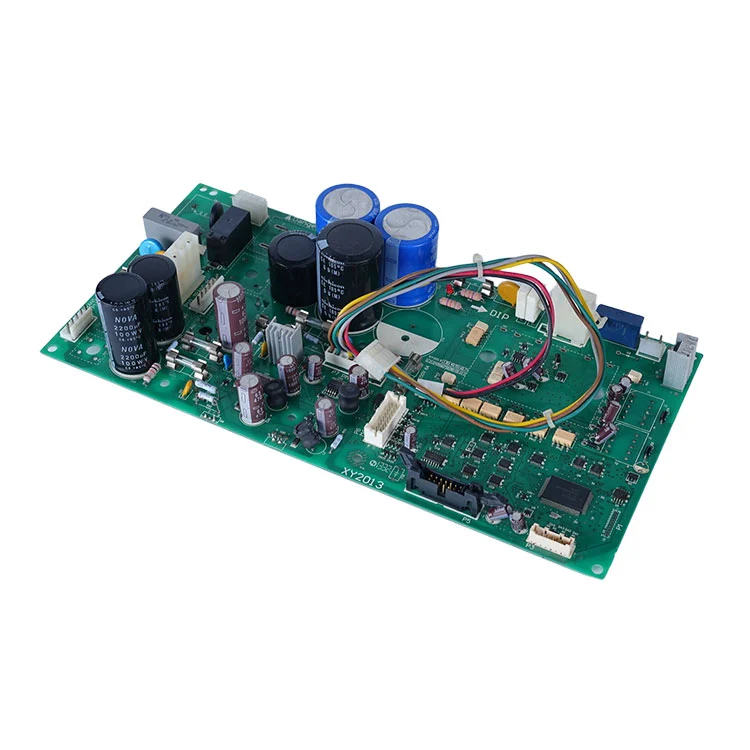
These parameters dictate the performance, durability, and reliability of each PCB. Manufacturers carefully select specifications based on end-use requirements. For instance, an automotive ECU PCB demands higher heat resistance and vibration tolerance compared to a simple household LED lighting board.

How Manufacturing Processes Ensure PCB Reliability

The reliability of a Printed Circuit Board does not only depend on design but also on precise manufacturing processes. High-quality PCBs require strict adherence to international standards such as IPC-A-600 (acceptability of printed boards). The process typically includes the following steps:

  1. Design & Layout – Engineers create the schematic and translate it into Gerber files, which dictate copper patterns, drill holes, and solder masks.

  2. Substrate Preparation – FR4 or chosen material is cut and laminated with copper foil.

  3. Image Transfer & Etching – Circuit patterns are printed and unwanted copper is etched away, leaving conductive pathways.

  4. Drilling & Plating – Holes are drilled for vias and component leads, then plated to ensure conductivity.

  5. Solder Mask Application – A protective polymer layer is applied, insulating traces and preventing solder bridging.

  6. Surface Finish – HASL (Hot Air Solder Leveling), ENIG (Electroless Nickel Immersion Gold), or other finishes are applied to improve solderability.

  7. Silkscreen Printing – Reference markings, logos, and labels are added.

  8. Electrical Testing – Flying probe or fixture-based testing ensures that all connections are valid and there are no shorts or open circuits.

  9. Final Inspection & Packaging – Boards are visually inspected, measured, and packaged according to customer requirements.

Reliability is further strengthened by techniques such as:

  • Impedance control for high-speed digital circuits.

  • Thermal relief pads to optimize soldering.

  • Microvia technology for compact HDI PCBs.

  • Conformal coatings for moisture and dust resistance.

Global manufacturers also implement quality management systems such as ISO 9001, ISO/TS 16949 (automotive), and AS9100 (aerospace). These ensure consistent performance and compliance with demanding industries.

How Printed Circuit Boards Shape Future Electronics

The future of PCBs continues to evolve with rapid technological trends. Emerging applications in 5G, AI-driven devices, electric vehicles, and IoT demand boards that are thinner, faster, and more durable. Innovations include:

  • HDI (High-Density Interconnect) PCBs: Allowing more components in smaller spaces, enabling smartphones and wearable technology.

  • Embedded Components: Integrating passive and active components directly within PCB layers for space savings.

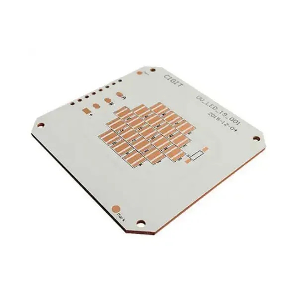
  • Metal Core PCBs: Using aluminum or copper bases for enhanced heat dissipation in LED lighting and power electronics.

  • Biodegradable Substrates: Responding to sustainability concerns, eco-friendly PCBs are gaining attention.

  • 3D-Printed PCBs: Offering flexible prototyping and customized geometries.

As industries demand higher frequencies, faster speeds, and better energy efficiency, PCB technology continues to adapt. Automotive electronics, for example, increasingly require boards capable of withstanding high vibration, wide temperature ranges, and electromagnetic interference control. Medical devices rely on miniaturized PCBs that maintain high reliability inside life-saving equipment. Telecommunications companies invest in high-frequency PCBs to ensure minimal signal loss in 5G base stations.

The impact of these innovations is profound: better connectivity, safer transportation, advanced healthcare, and more efficient energy use. In essence, the evolution of Printed Circuit Boards directly influences the future of global technology infrastructure.

Frequently Asked Questions (FAQs)

Q1: How long does a Printed Circuit Board last?
A high-quality PCB can last anywhere from 10 to 20 years depending on usage conditions, material selection, and thermal management. Industrial and aerospace-grade PCBs, designed with stricter specifications, may last even longer with proper maintenance.

Q2: How do I choose the right PCB for my application?
Choosing the right PCB involves assessing the operating environment, power requirements, signal speed, and physical design constraints. For instance, flexible PCBs are ideal for wearable devices, while multilayer rigid boards are better for high-speed data processing systems. Consulting with an experienced manufacturer ensures optimal material and design choices.

Printed Circuit Boards are the hidden force behind modern technology, ensuring that devices remain functional, reliable, and efficient. From the basic single-layer designs of consumer gadgets to the sophisticated multilayered structures in aerospace and medical equipment, PCBs continue to evolve and adapt to new challenges.

At Fanway, we combine advanced technology, strict quality standards, and industry expertise to deliver PCBs that meet diverse global demands. If you are looking for a trusted partner to support your electronics manufacturing needs, contact us today and discover how we can power your innovation.

Related News
X
We use cookies to offer you a better browsing experience, analyze site traffic and personalize content. By using this site, you agree to our use of cookies. Privacy Policy
Reject Accept