Shenzhen Fanway Technology Co., Ltd.
News

News

What is the function of HDI PCB?

High-Density Interconnect (HDI) printed circuit boards (PCBs) have become a cornerstone in modern electronics, especially in applications where compactness, high performance, and reliability are critical. From smartphones and tablets to aerospace electronics and medical devices, HDI PCBs offer unique advantages over conventional printed circuit boards.

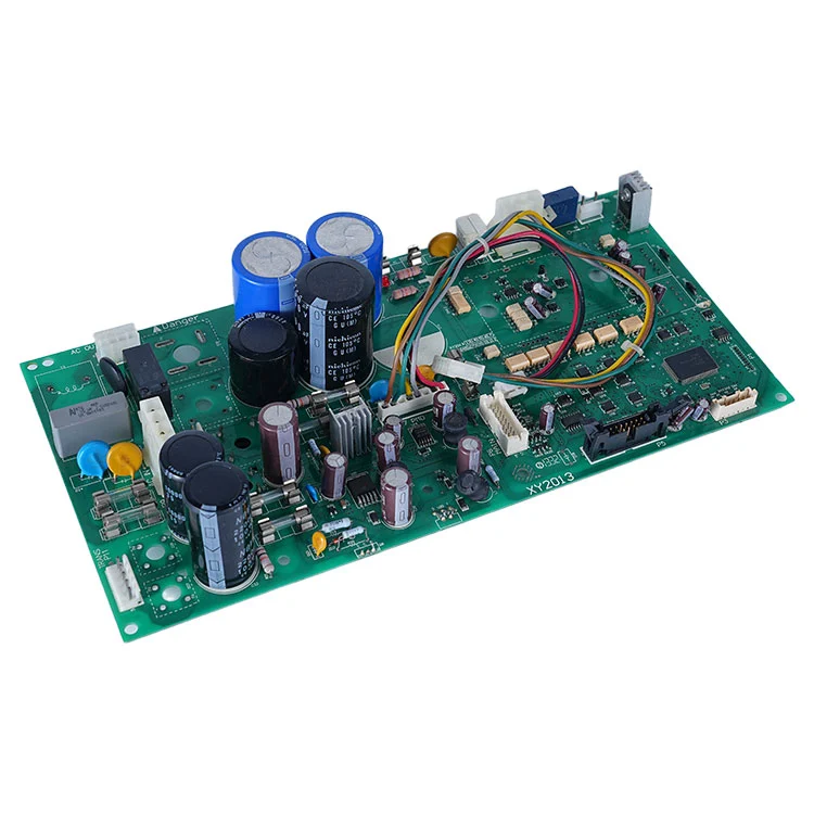
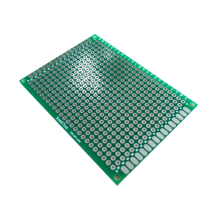
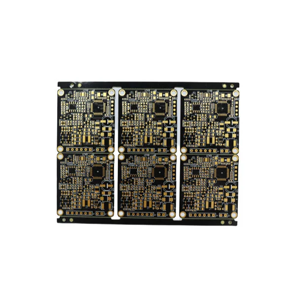
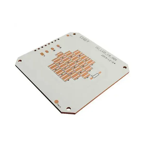
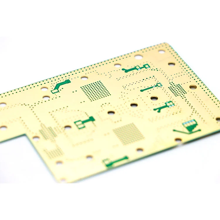
HDI PCB

HDI PCBs are advanced printed circuit boards that feature a higher wiring density per unit area than traditional PCBs. Unlike standard PCBs, which may have simple through-hole technology and larger traces, HDI PCBs utilize microvias, blind vias, and buried vias to create highly efficient interconnections.

Key characteristics that distinguish HDI PCBs include:

  • Microvias: Extremely small vias, typically less than 150 microns in diameter, which connect different layers without taking excessive space.

  • Blind and Buried Vias: Blind vias connect external layers to inner layers, while buried vias interconnect internal layers without reaching the surface.

  • High Wiring Density: More interconnections per unit area allow for compact designs and better signal integrity.

  • Fine Line/Space Patterns: Lines as narrow as 3 mils and spacing as low as 3 mils enable more routing options in a limited space.

These features allow HDI PCBs to support high-speed signal transmission and reduce parasitic effects, making them ideal for applications where performance cannot be compromised.

HDI PCB Key Parameters

Below is a professional summary of HDI PCB technical specifications for quick reference:

Parameter Typical Value / Range Description
Substrate Material FR4, Rogers, PTFE Determines thermal performance and signal integrity
Layers 4–20 layers Number of layers can be customized based on application
Microvia Diameter 0.10–0.15 mm Small via to reduce space usage and maintain high density
Via Type Blind, Buried, Through Connects layers efficiently without increasing board size
Line Width / Spacing 3–5 mil Fine line capability for dense routing
Copper Thickness 0.5–3 oz/ft² Supports high current and thermal management
Surface Finish ENIG, HASL, OSP Ensures solderability and long-term reliability
Min Board Thickness 0.4–1.6 mm Allows thinner designs for compact devices
Signal Integrity Controlled impedance available Critical for high-speed digital and RF applications
Thermal Performance Tg 130–180°C, HDI-specific FR4 Ensures stability under high thermal stress

Why Are HDI PCBs Essential in Modern Electronics?

As devices shrink in size but demand higher processing power, the need for advanced interconnect technologies like HDI becomes more pressing. Standard PCBs often face limitations in routing and signal integrity, making them less suitable for devices with complex functionality. HDI PCBs address these challenges in several ways:

  1. Enhanced Signal Performance: The shorter and more direct signal paths reduce inductance and capacitance, which minimizes signal loss and crosstalk.

  2. Compact Design: With higher wiring density and microvias, HDI PCBs enable smaller devices without sacrificing functionality.

  3. Improved Reliability: Fewer layers of routing and better thermal management decrease the risk of failure under high-frequency operations.

  4. Cost Efficiency for High-Volume Production: Despite initial manufacturing costs, HDI PCBs reduce the need for multiple PCBs in a single device, simplifying assembly and lowering overall costs.

  5. Support for Advanced Components: HDI technology is essential for mounting high-pin-count components like BGA (Ball Grid Array), CSP (Chip Scale Package), and other fine-pitch ICs.

The rapid evolution of smartphones, wearable devices, automotive electronics, and medical instrumentation has made HDI PCBs a critical choice for manufacturers seeking performance without increasing device size.

How Are HDI PCBs Manufactured to Meet Advanced Specifications?

Producing HDI PCBs involves advanced fabrication techniques that require precise control over materials, processes, and quality assurance. The key steps in HDI PCB manufacturing include:

  1. Material Selection: Substrates with high thermal stability and low dielectric loss are chosen based on application requirements. Common materials include high-Tg FR4, Rogers, and PTFE laminates.

  2. Lamination Process: Multiple layers are laminated together using high-pressure and temperature to ensure perfect adhesion and electrical isolation.

  3. Microvia Drilling: Laser drilling is commonly used for microvias, allowing diameters as small as 0.10 mm. This step requires extreme precision to avoid misalignment or damage.

  4. Copper Plating: Copper is electroplated to fill vias and form conductive paths. The thickness is carefully controlled to support current carrying capacity.

  5. Patterning: Advanced photolithography defines fine line/space patterns, ensuring accurate and dense routing.

  6. Surface Finishing: ENIG, OSP, or HASL finishes are applied to ensure solderability and long-term reliability.

  7. Electrical Testing: Each board undergoes rigorous testing for continuity, impedance, and shorts to guarantee compliance with design specifications.

The combination of these processes ensures that HDI PCBs can reliably support high-speed signals, high-density components, and demanding thermal conditions.

Common Questions About HDI PCBs

Q1: What applications benefit the most from HDI PCBs?
A1: HDI PCBs are ideal for high-performance devices where space constraints and signal integrity are critical. This includes smartphones, tablets, wearable electronics, medical devices, aerospace equipment, automotive electronics, and high-speed networking hardware. Their ability to handle fine-pitch components and complex interconnections makes them superior in such scenarios.

Q2: How does HDI PCB reliability compare to conventional PCBs?
A2: HDI PCBs provide enhanced reliability due to shorter interconnect paths, reduced signal loss, better thermal performance, and fewer soldering points in high-density assemblies. These factors reduce the risk of electrical failure, signal degradation, and thermal stress, making HDI PCBs suitable for mission-critical applications where conventional PCBs may fail.

What Makes Fanway HDI PCBs a Preferred Choice in the Market?

At Fanway, HDI PCB manufacturing is aligned with industry-leading standards and strict quality control. Fanway specializes in high-density, multi-layer PCBs that combine performance, durability, and scalability for both prototype and mass production. Key differentiators of Fanway HDI PCBs include:

  • Customization: Tailored layer count, substrate material, and line/space specifications to meet project-specific requirements.

  • Advanced Fabrication Capabilities: Laser-drilled microvias, fine line patterning, and controlled impedance options.

  • Rapid Turnaround: Streamlined production processes allow fast prototyping and timely delivery for market-critical projects.

  • Quality Assurance: Every board undergoes electrical testing, optical inspection, and functional verification to ensure zero defects.

  • Technical Support: Fanway provides comprehensive technical consultation to optimize designs for manufacturability, performance, and cost efficiency.

For businesses looking to integrate high-performance HDI PCBs into their products, Fanway offers reliable solutions that maintain excellence from prototyping to full-scale manufacturing.

Contact us today to explore customized HDI PCB solutions and elevate your product designs to the next level.

Related News
X
We use cookies to offer you a better browsing experience, analyze site traffic and personalize content. By using this site, you agree to our use of cookies. Privacy Policy
Reject Accept