Shenzhen Fanway Technology Co., Ltd.
News

News

Why chosse Mixed PCB Assembly?

2025-08-21

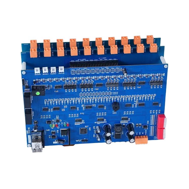
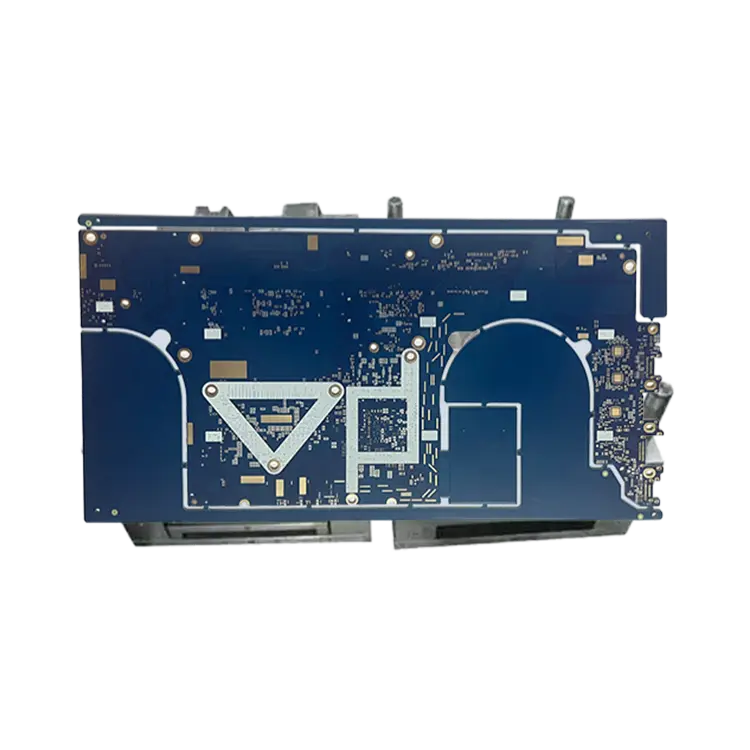
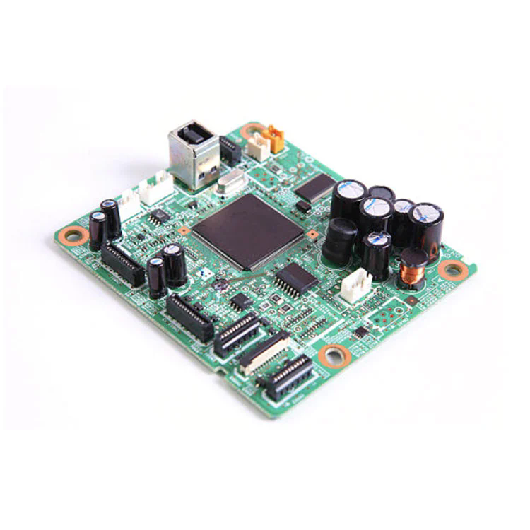
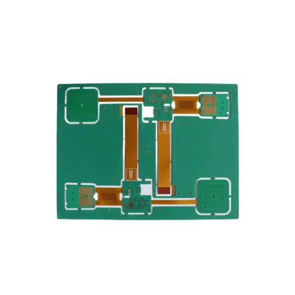
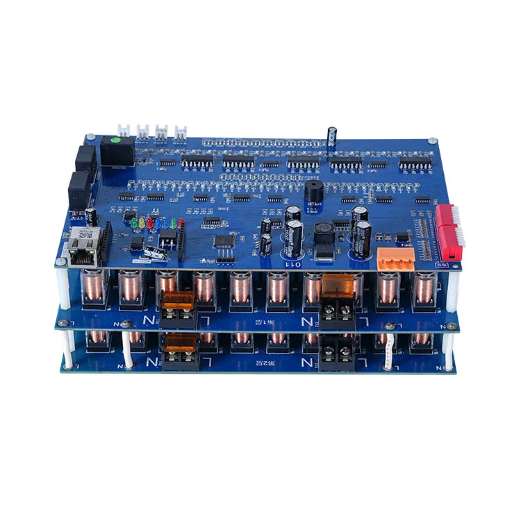
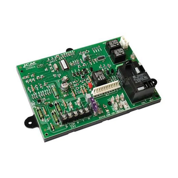
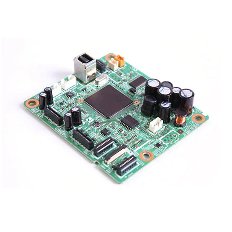
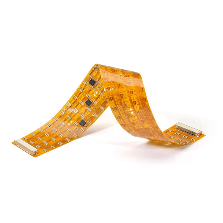
In today’s fast-evolving electronics world, the ability to blend multiple PCB technologies—rigid, flex, rigid-flex—into a single, integrated solution has become critical. Mixed PCB Assembly is gaining prominence because it enables:

  • Compact, lightweight design: Merges rigid and flexible substrates for space-saving form factors.

  • Improved durability and reliability: Flex layers absorb mechanical stress, reducing failure.

  • Cost efficiency: Combines processes to reduce assembly steps, sourcing, and inventory.

Current Google search trends reveal high demand for terms like “mixed PCB assembly services,” “rigid-flex PCB assembly,” and “flex to rigid PCB integration.” By structuring this article around the central What query—“What makes Mixed PCB Assembly indispensable for today’s electronics?”—we align closely with user search intent and trending topics.

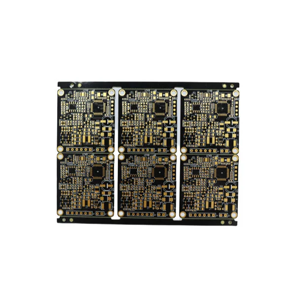
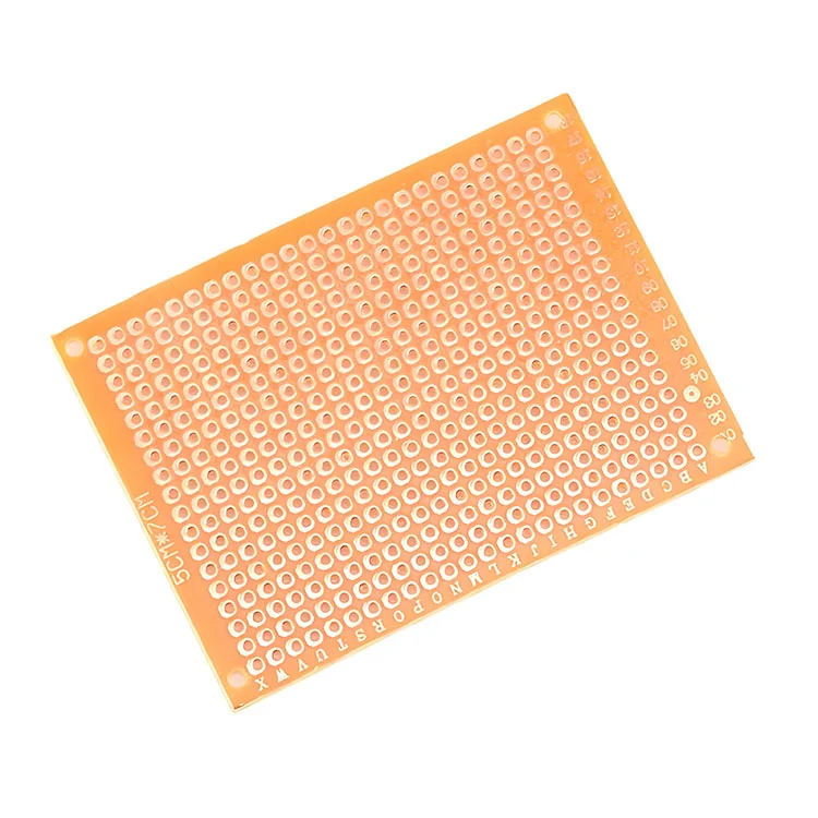
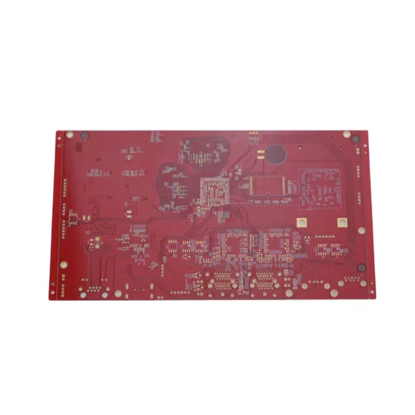
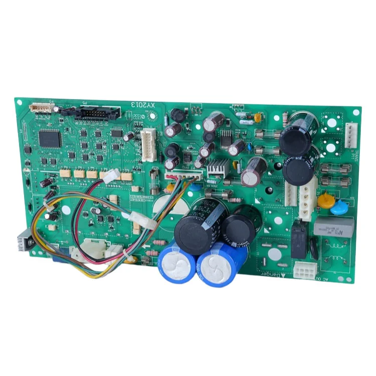
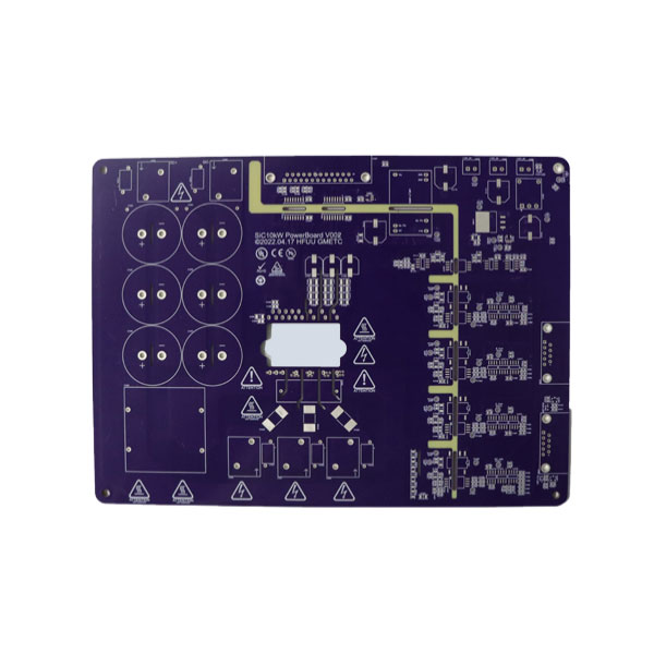
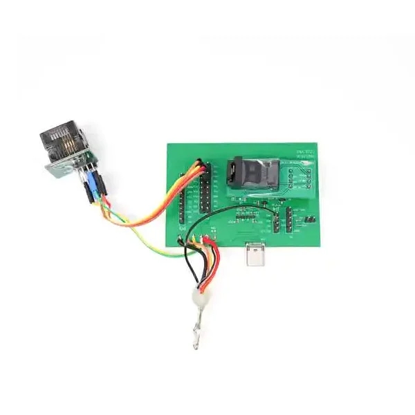
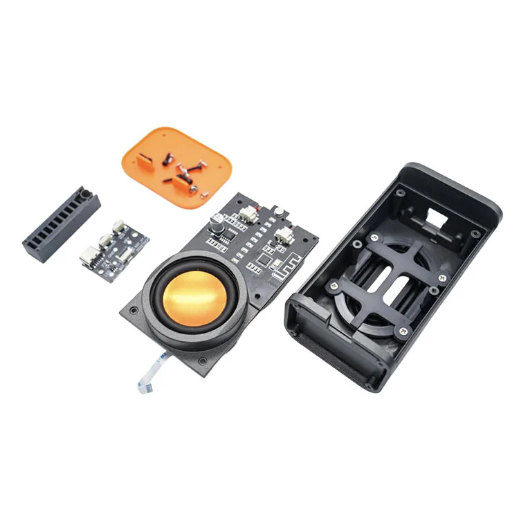
Mixed PCB Assembly

Product Deep Dive – Technical Parameters of Mixed PCB Assembly

Below is a consolidated overview (in table form) offering a detailed snapshot of Mixed PCB Assembly specifications. This demonstrates our professionalism and clarity.

Feature Specification / Description
Substrate Types Rigid FR-4 layers, polyimide flex layers, rigid-flex configurations
Layer Count Up to 20 layers (mix of rigid + flex); typical stack: rigid 6-8 + flex 2-4
Minimum Trace/Space Rigid: 4 mil/4 mil; Flex: 3 mil/3 mil
Via Types Through-hole vias (THV), microvias (diameter ≥ 50 µm), buried and blind vias
Copper Thickness 1 oz (typical); up to 3 oz heavier copper for high-current flex segments
Flex Bend Radius ≥ 10× thickness, standard: ≥ 0.5 mm bend radius for 0.05 mm flex thickness
Solder Mask Flexible solder mask for flex areas, rigid mask for FR-4; seamless transition
Assembly Components Surface-mount, through-hole, mixed SMT/THT components; flex zones may include stiffeners
Thermal Management Embedded copper planes and thermal vias to manage hotspot areas
Quality Standards IPC-6013 (flex), IPC-6012 (rigid), IPC-6018 (rigid-flex), IPC-A-600 class 2; RoHS / REACH compliance

In-Depth Exploration – What Key Considerations Are Vital for Mixed PCB Assembly?

What are the most critical design and process considerations when planning a Mixed PCB Assembly?

  1. Material Compatibility & Stack-up Planning
    The interplay between rigid FR-4 and flexible polyimide layers must be carefully engineered to avoid delamination during flex. Controlling the coefficient of thermal expansion (CTE) across layers ensures long-term reliability through thermal cycles.

  2. Trace and Via Integrity in Flex Zones
    Flex zones demand tighter tolerances: thinner copper layers, controlled trace/space, and optimized via design (e.g. filled and plated microvias) to resist fatigue from bending.

  3. Bend Radius, Flex Life, and Mechanical Stress
    Specifying proper bend radii (≥ 10× thickness) and conducting flex-life testing under intended dynamic conditions ensures the flex sections endure operational movement.

  4. Stiffener Integration for Component Assembly
    Temporary or permanent stiffeners (e.g., FR-4 sheets or adhesive-backed polyimide) are often used to simulate rigid support during SMT/THT assembly on flex zones, ensuring accurate placement and soldering, then removed if needed.

  5. Thermal & Signal Routing
    Mixed PCBs often combine high-power or RF circuitry. Proper thermal via arrays and ground planes, paired with careful layer assignment, maintain signal integrity and heat dissipation.

  6. Manufacturability & Cost Trade-Offs
    Balancing complexity vs. cost: increasing layer counts, microvias, or heavy copper raises price. Early DFM (Design for Manufacturability) reviews are essential to validate feasibility and cost-effectiveness.

  7. Testing & Inspection Capabilities
    Mixed designs may limit standard AOI or X-ray; custom fixtures, flex-friendly test jigs, or flying probe testing may be required to validate connectivity and component placement.

Mixed PCB Assembly FAQs – Expert Q&A


Q1: What is Mixed PCB Assembly used for?
A1: It’s employed where rigid-only solutions fall short—like wearables, foldable devices, medical implants, aerospace sensor arrays—any application demanding flexibility, compactness, and reliability.

Q2: How can you ensure reliability across flex-rigid transitions?
A2: Through careful stack-up design (matching CTE), controlled bend radii, epoxy or adhesive bonding in transition zones, proper via plating, and testing under simulated mechanical cycles.

Brand Integration with Contact Call-to-Action

Mixed PCB Assembly stands at the forefront of modern electronics design—delivering unmatched integration of rigid and flexible technologies. The key lies in meticulous stack-up planning, trace/via precision, mechanical flex testing, DFM analysis, and stringent QA to ensure both performance and cost viability.

When done correctly—leveraging expert design rules, robust materials, and precise manufacturing—Mixed PCB Assembly unlocks new product possibilities in advanced wearables, medical, aerospace, automotive, and consumer devices.

At Fanway, we bring over two decades of expertise in advanced PCB and rigid-flex fabrication. Our Mixed PCB Assembly services combine high-quality materials, industry-leading standards (IPC compliance, RoHS/REACH), and tailored DFM support to achieve durable, high-performance solutions at scale.

Whether you’re prototyping or ramping to high-volume production, our team ensures design-to-delivery excellence. Contact us today to elevate your product designs with precision-engineered Mixed PCB Assembly solutions.

Related News
X
We use cookies to offer you a better browsing experience, analyze site traffic and personalize content. By using this site, you agree to our use of cookies. Privacy Policy
Reject Accept